🛠️ Custom PCB Projects
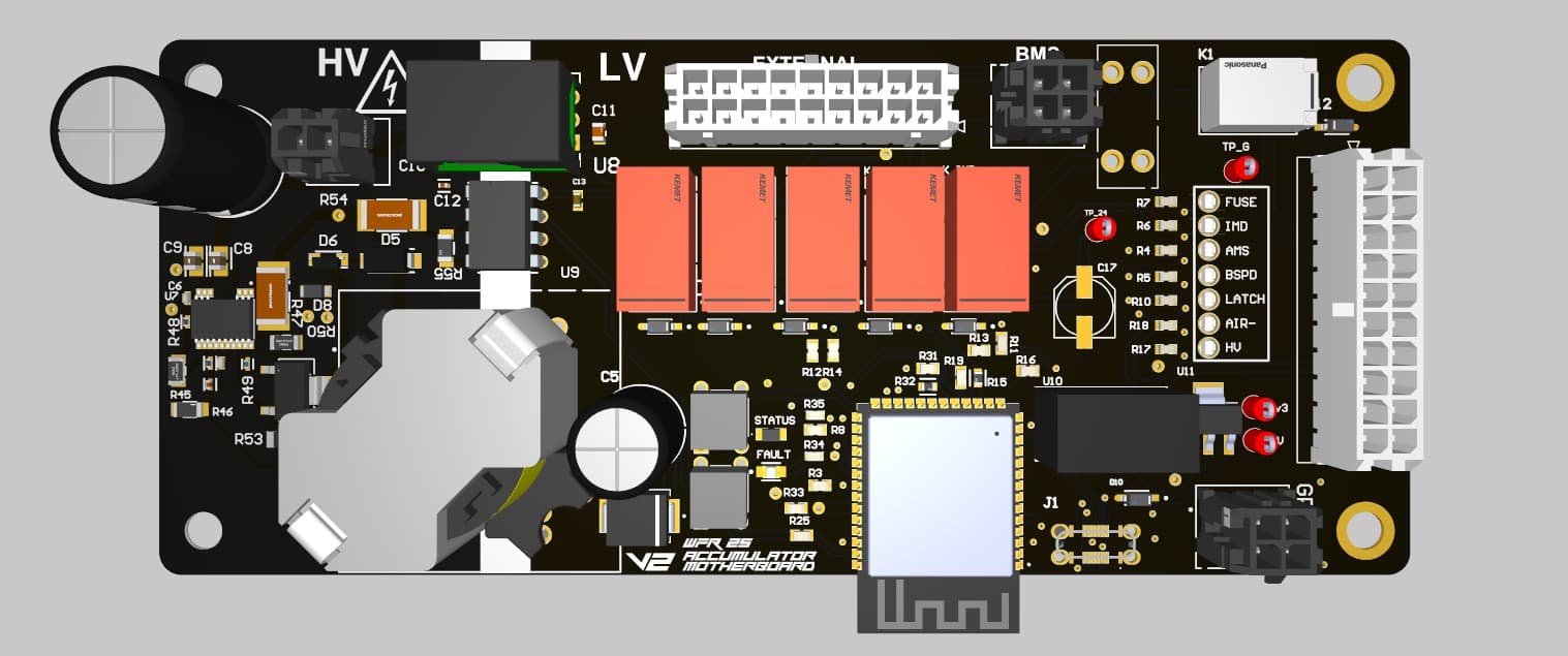
MOBO – High Voltage Control Board

I worked on the software and system control logic for the **high-voltage portion** of our Accumulators Motherboard. This included:
- Implementing precharge sequence logic and shutdown interlocks
- Implementing a Voltage Indicator light on the Accumulator Container
- Managing contactor state transitions and fault detection
- Simulating precharge/indicator light timing and current ramp in LTspice for the flyback circuit
On the Low Voltage end; I was involved in reviewing the hardware and testing
🧩 Schematic
As part of the power system, I worked on implementing a robust flyback converter using the LT8316IFE#PBF from Analog Devices. Designing a flyback involves careful selection of the transformer turns ratio, snubber network for transient suppression, and proper compensation for control loop stability. I also had to manage inrush current control and soft-start behavior by configuring external passives and validating waveforms under different loading conditions.
Attention to layout was critical — especially for high di/dt switching paths and grounding. I followed best practices for minimizing EMI, ensuring that the transformer, MOSFET, and output diode switching loops were tight and well-shielded. I also verified performance through both simulation and bench testing using differential probes and current shunts.
The associated precharge circuitry was designed using an isolated op-amp for safe HV voltage monitoring and feedback control. This allowed the system to track precharge progress across an isolation boundary and safely trigger the main contactor once the voltage reached acceptable levels. Key skills applied here included analog design, power supply topology understanding, component derating, and safety-focused design methodology.

📈 qSimulation
Since the flyback operates at high voltage, I simulated the circuit in LTspice to validate behavior before any physical testing. This allowed me to safely evaluate switching transients, snubber effectiveness, and transformer performance without risking hardware damage or personal safety. Simulation was a critical step to ensure the design was stable, efficient, and safe to implement.
BSPD – Brake System Plausibility Device

I designed the BSPD to detect implausible braking behavior based on brake pressure and current input. Key features:
- Comparator-based detection circuit
- Analog filtering for noise reduction
- Analog Signal delay, to prevent false tripping
The board was built to meet Formula SAE shutdown safety rules and is heavilty inspected at competions.
🧩 Schematic
The BSPD schematic uses a comparator-based & logic gate circuit to watch for invalid acceleration/braking conditions, or detecting invalid sensor inputs (potentially from internal/external shorts) and triggers a shutdown latch via MOSFET logic when appropriate.


📈 Simulation
Simulations were done on falstad to ensure, comparator logic was correct and that false trips were being prevented by the shutdown circuit.
TSSI – Tractive System Status Indicator

The TSSI is a simple but critical safety component. The TSSI gives us the status that the vehicle is in with respect to FSAE rules.
🧩 Schematic
The schematic follows rules abiding logic using low-side and high-side drivers paired with a 555 timer (used for LED flashing) to give the status of the vehicle.
